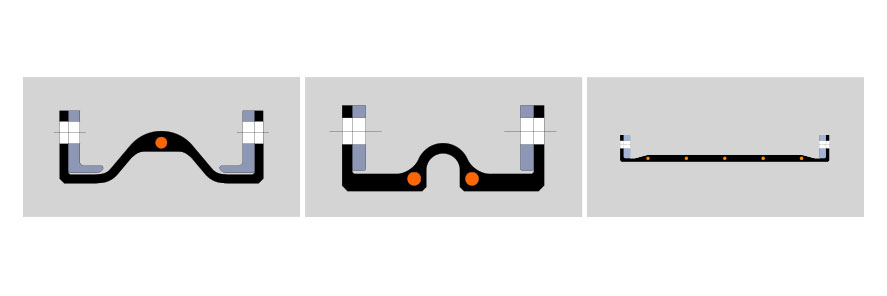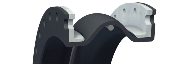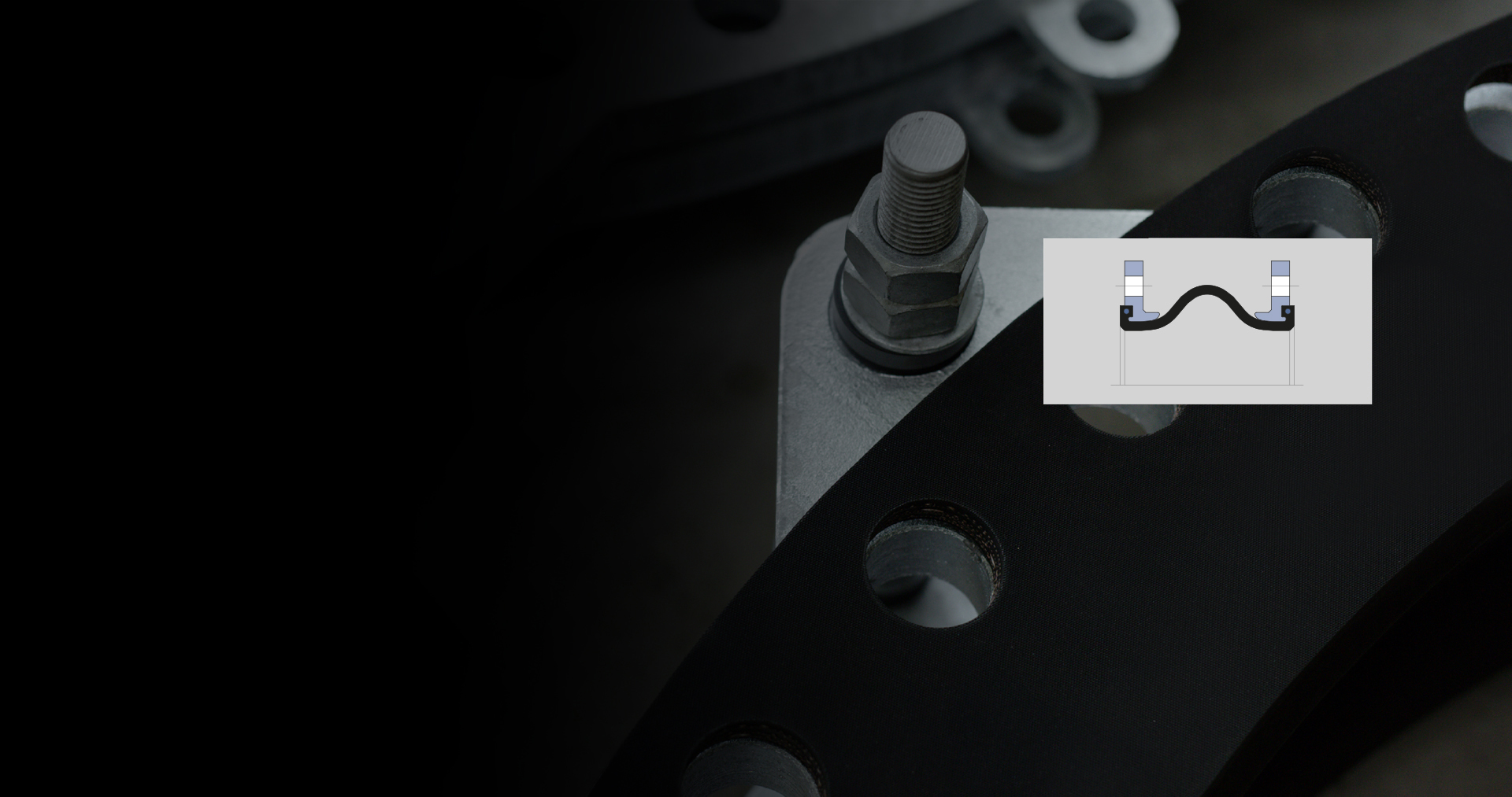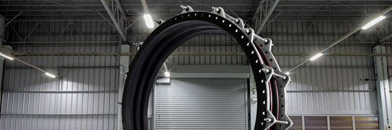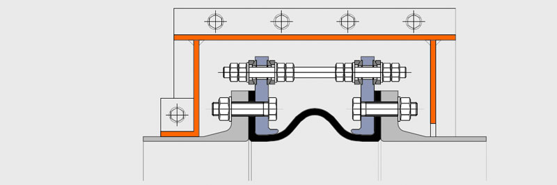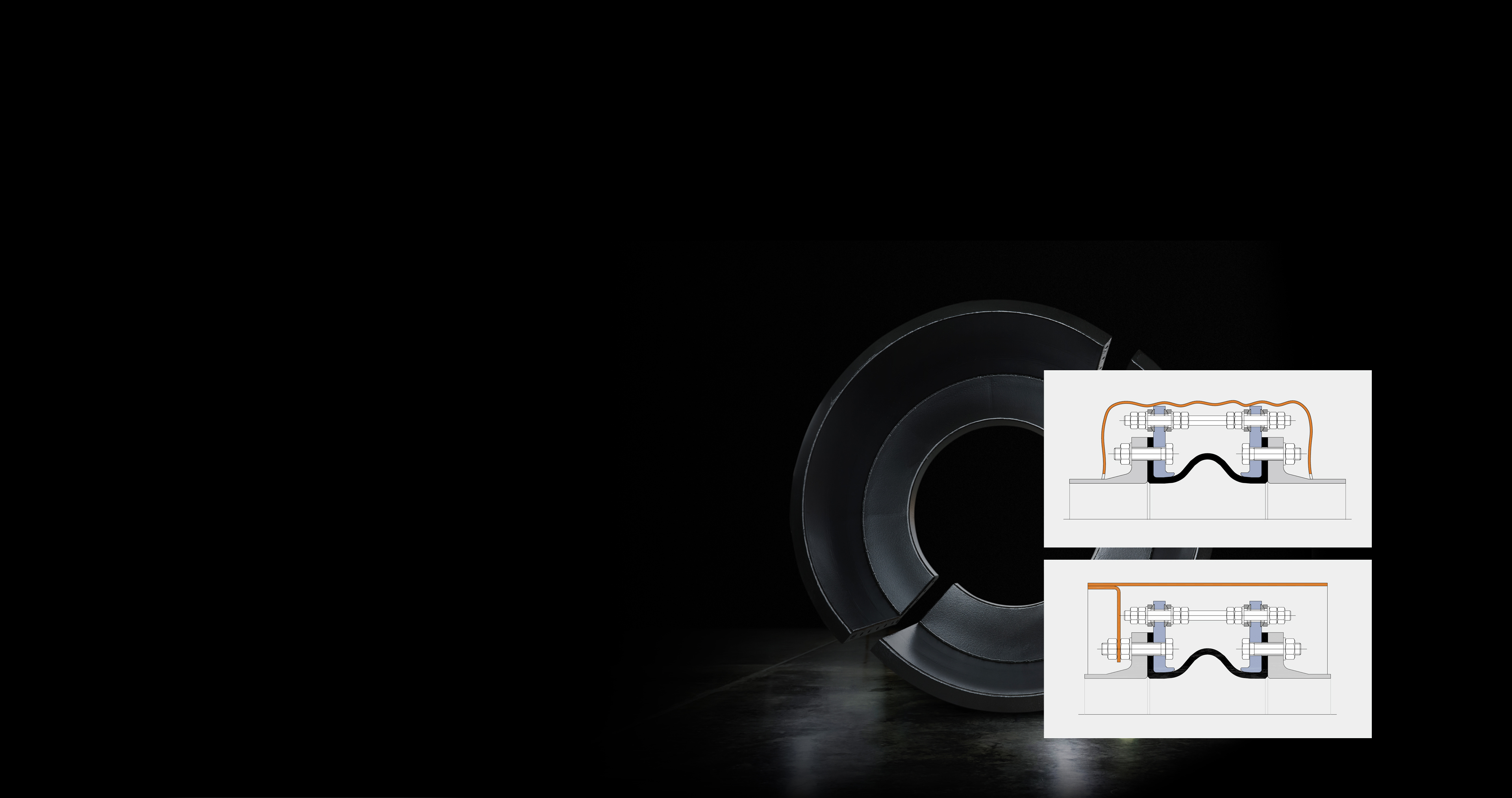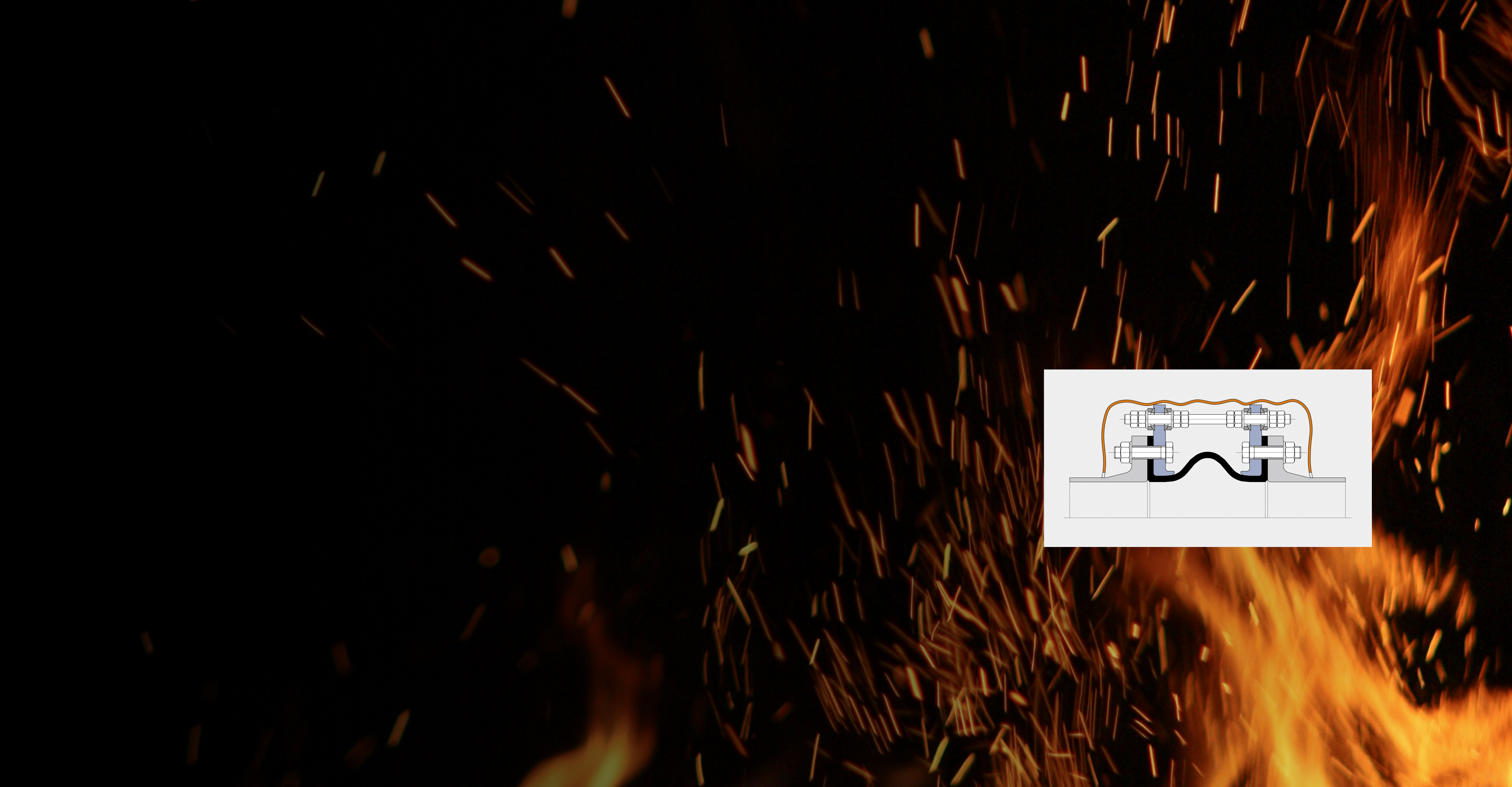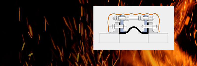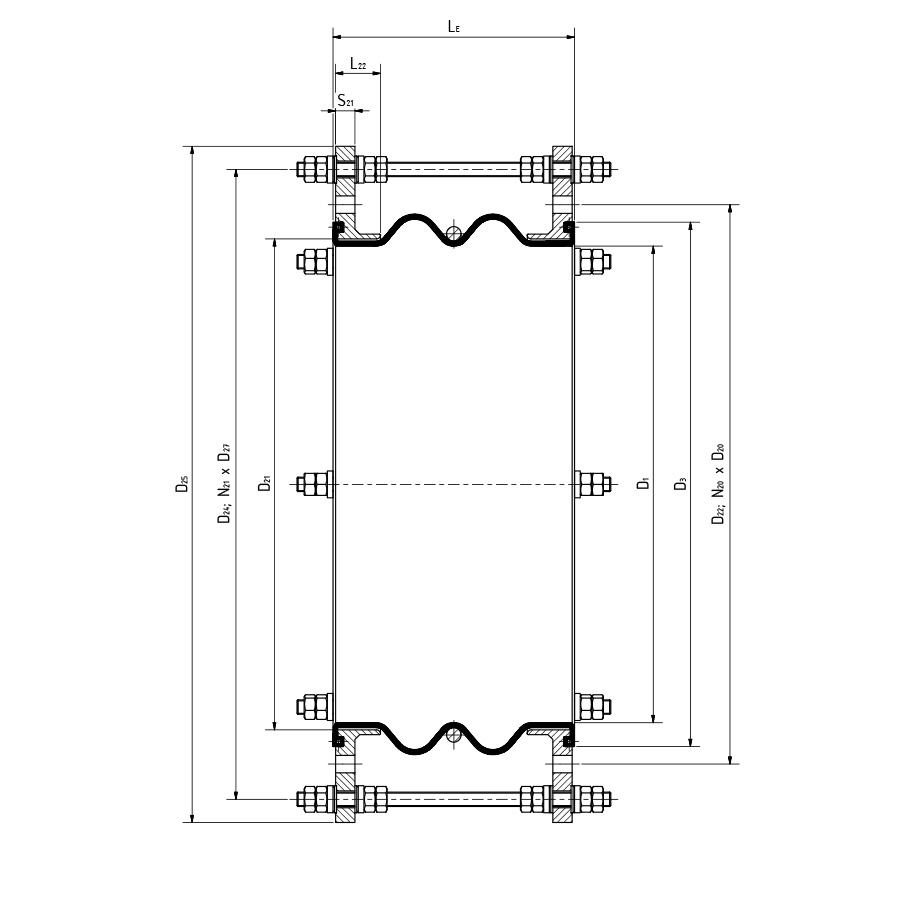


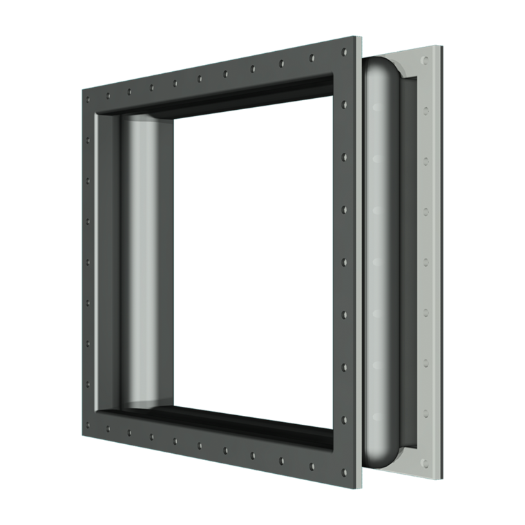
Lateral expansion joint
with two arches
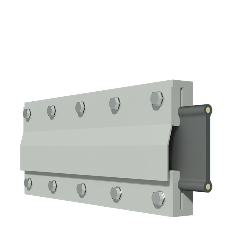
Lateral expansion joint
without arch
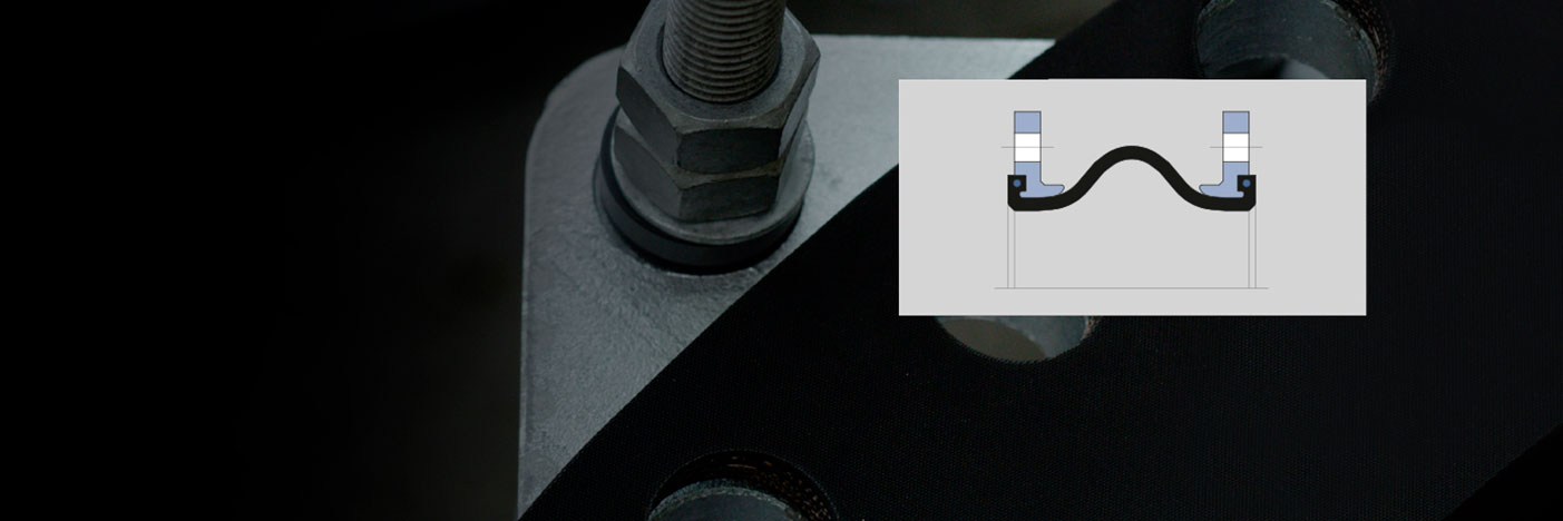
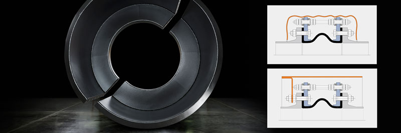
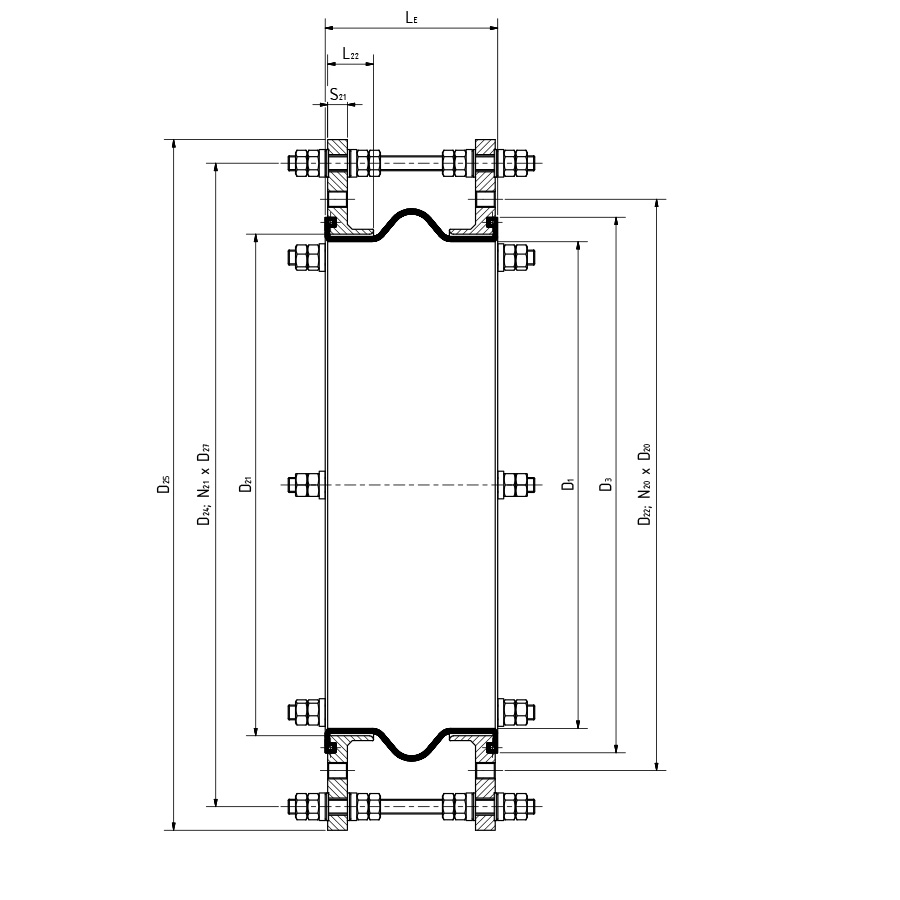
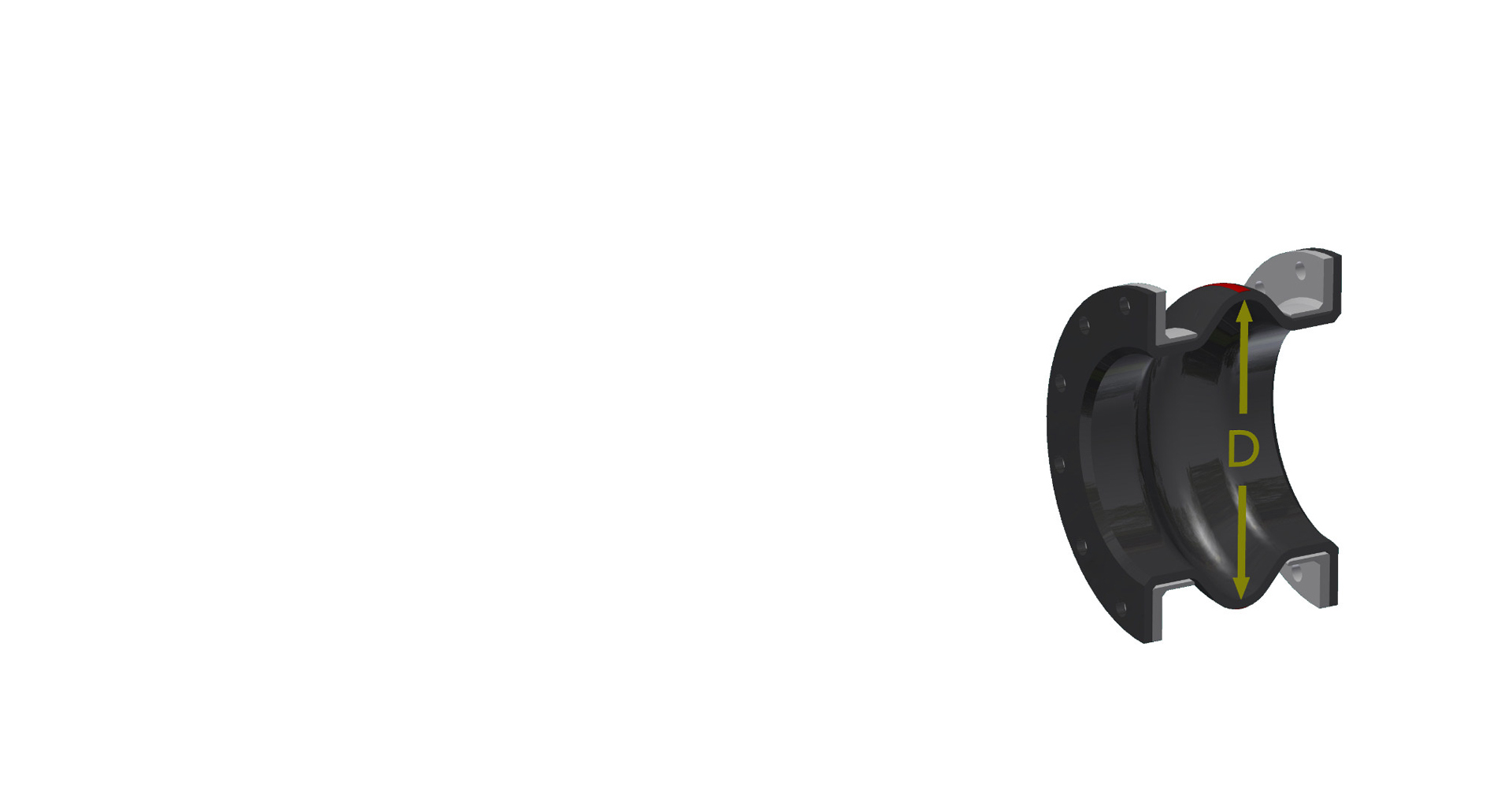
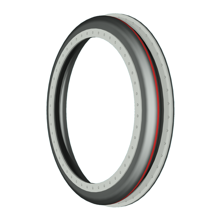
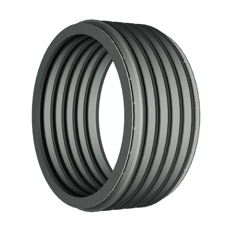
Lateral expansion joint
with one arch
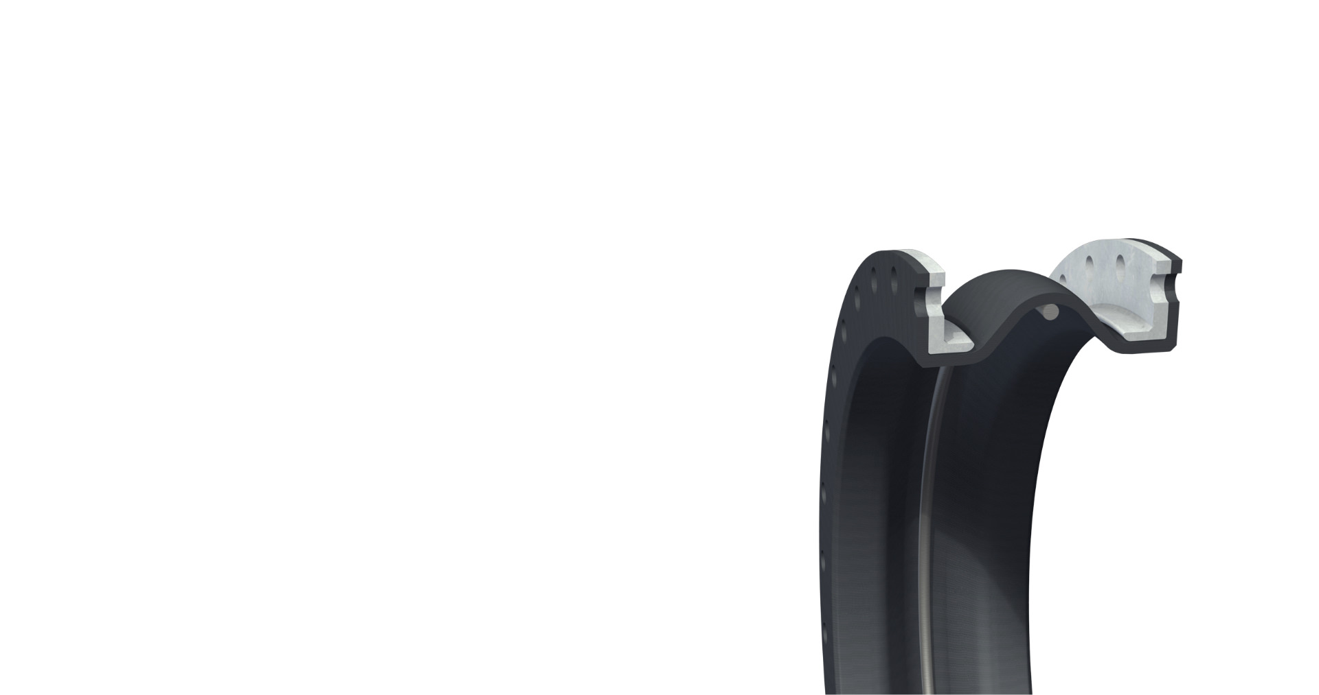
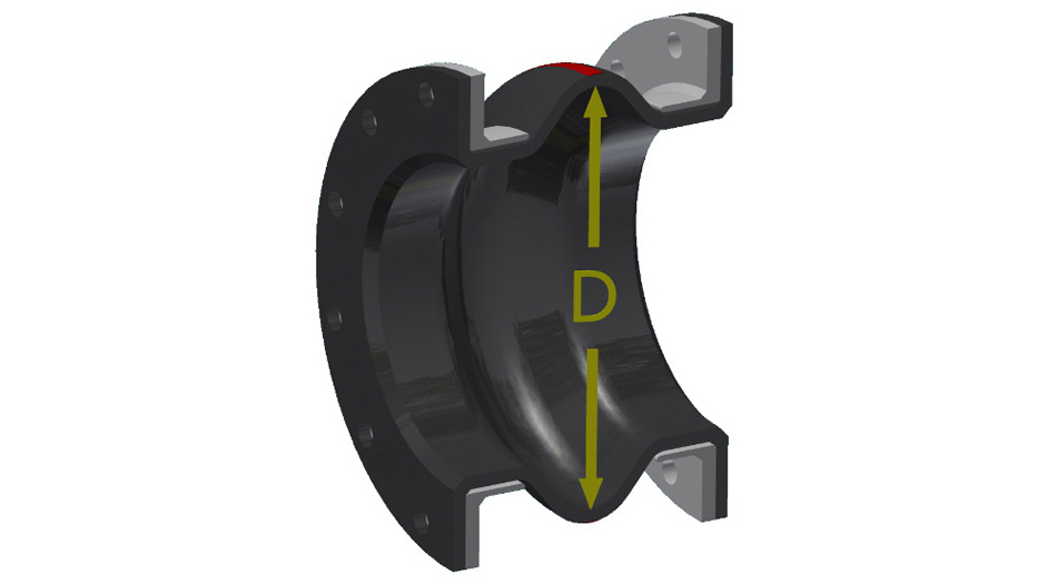
Lateral expansion joint
with one arch
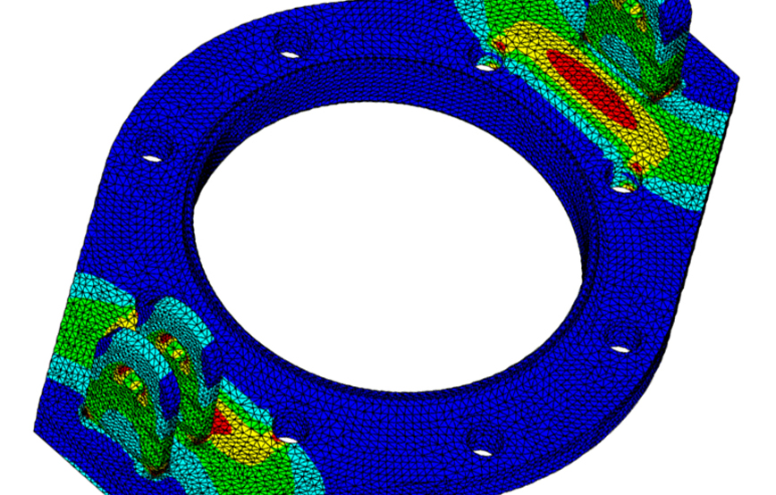
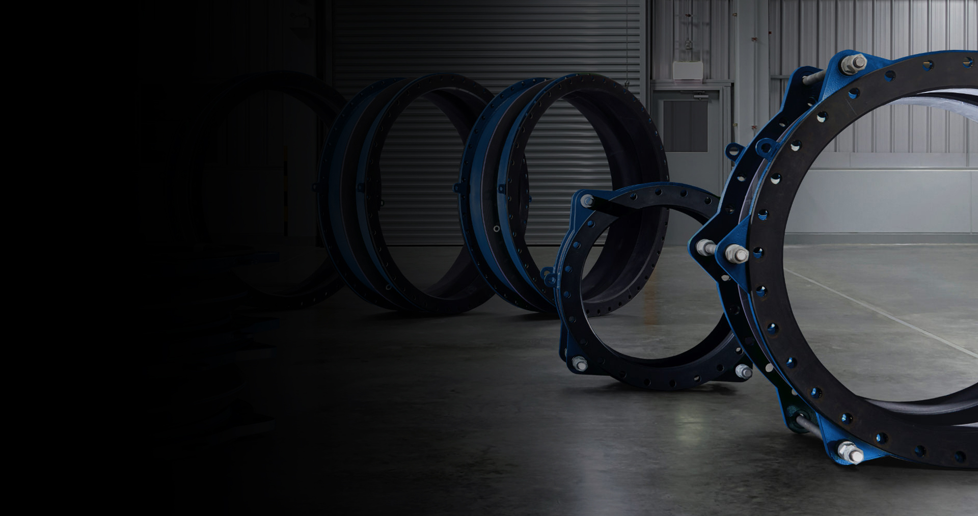
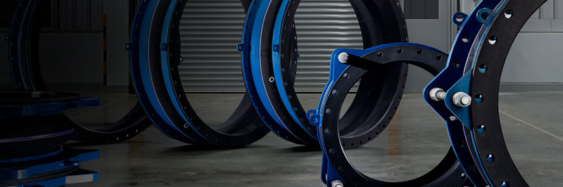
Thermal movements along with other external forces and displacements, including ground settlement can quickly exceed allowable pipe and anchor stresses. Rubber expansion joints absorb these stresses and replace them with their own low stiffness (spring rate).
The inherent flexibility of rubber expansion joints permits almost unlimited flexing to recover from imposed movements, requiring relatively less force to move, thus preventing damage to motion equipment. When expansion joints are installed in the pipeline, the static portion of the thrust is calculated as a product of the area of the inner diameter of the arch of the expansion joint times the maximum pressure that will occur with the line. The result is a force expressed in Newton which causes stress on the adjacent pipeline anchors.
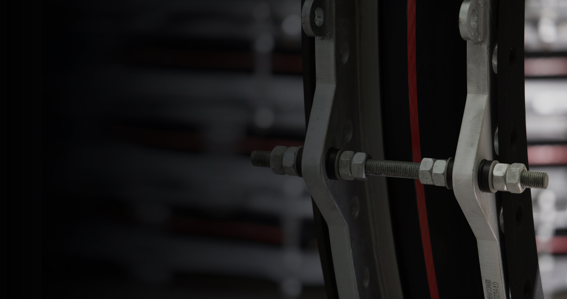
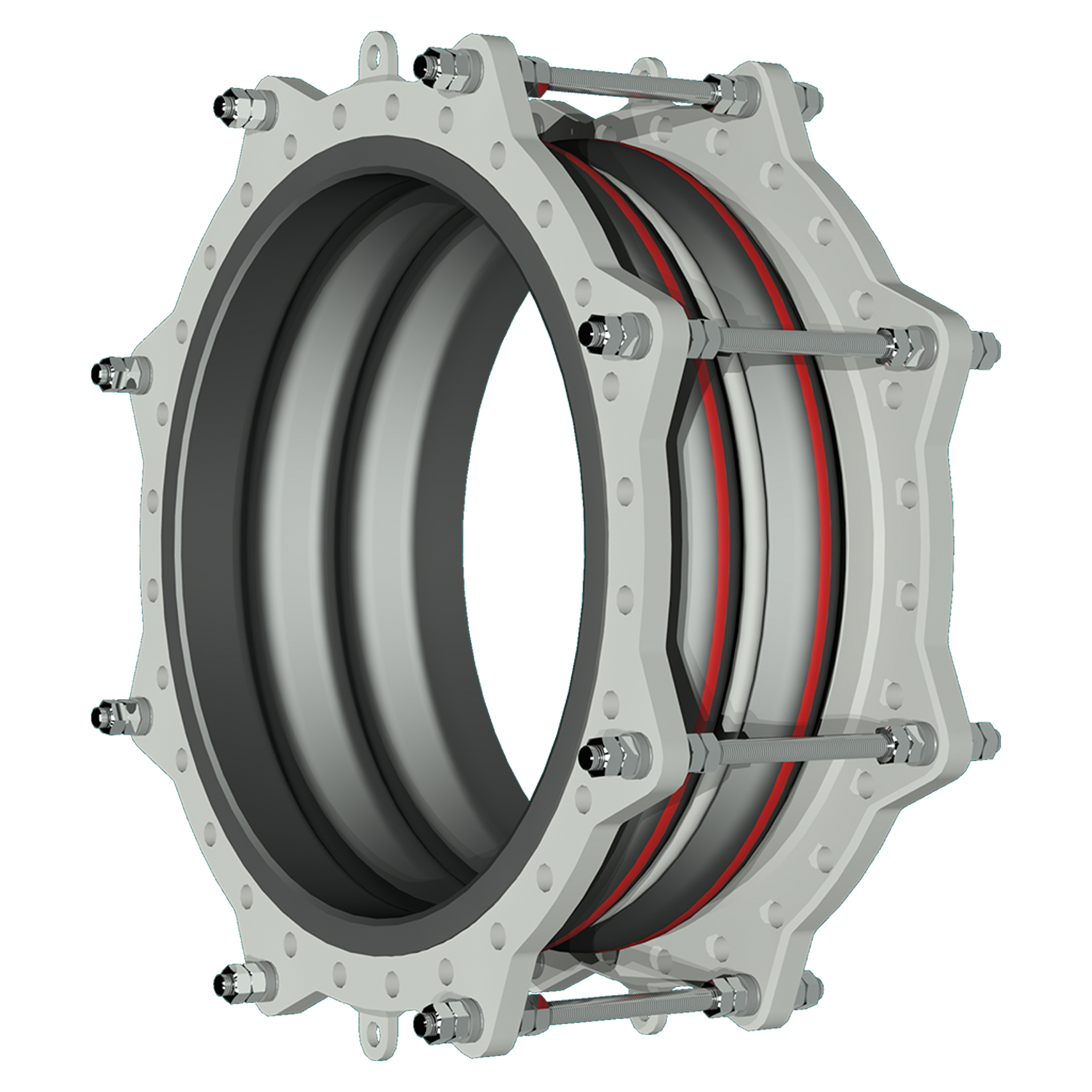
Lateral expansion joints receive two or more tie-rods across the expansion joint axis from flange to flange to take the full pressure thrust so that no thrust is transferred onto adjacent pipeline anchors, guides or equipment anymore.
In order to reduce the forces, a lower arch can be used in case of small movements.

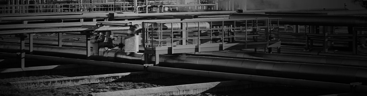
Of course, we are also available to you as a contact partner for individual requirements and applications.
This also applies to seemingly impossible cases - whether complex designs, special operating conditions
or extraordinary dimensions. Please contact us.


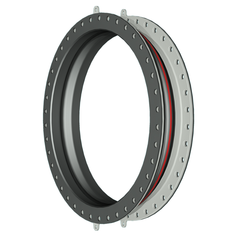
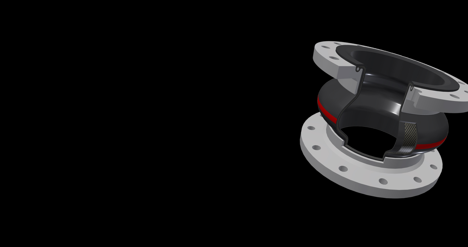
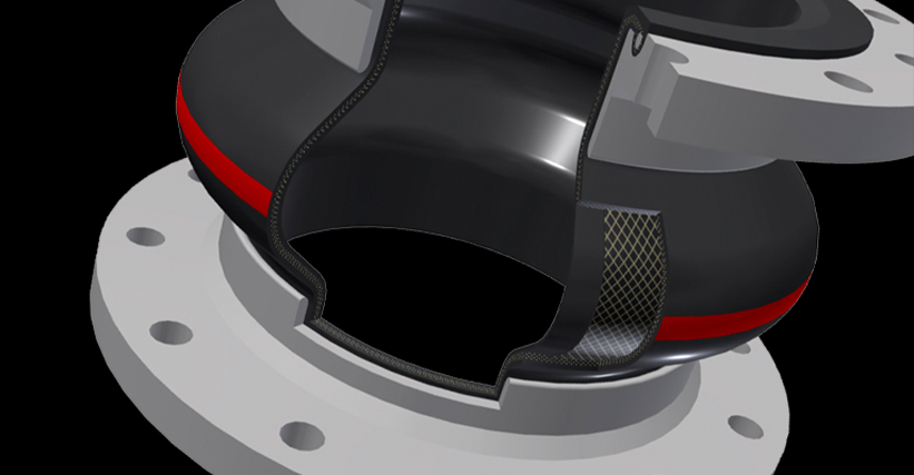
Universal expansion joints are installed in piping systems that are anchored on both sides of the joint. This construction represents the most cost-effective arrangement when used in rigid piping systems with main anchors and numerous guides at specific spacing. They come as cylindrical, single, or multiple arch expansion joints with full faced rubber flanges, swivel flanges or as slip-on sleeves.

200 to 4,000 mm
6,000 x 3,000 mm
standard 150 to 250 mm
up to 2.50 bar
with external pressure stability
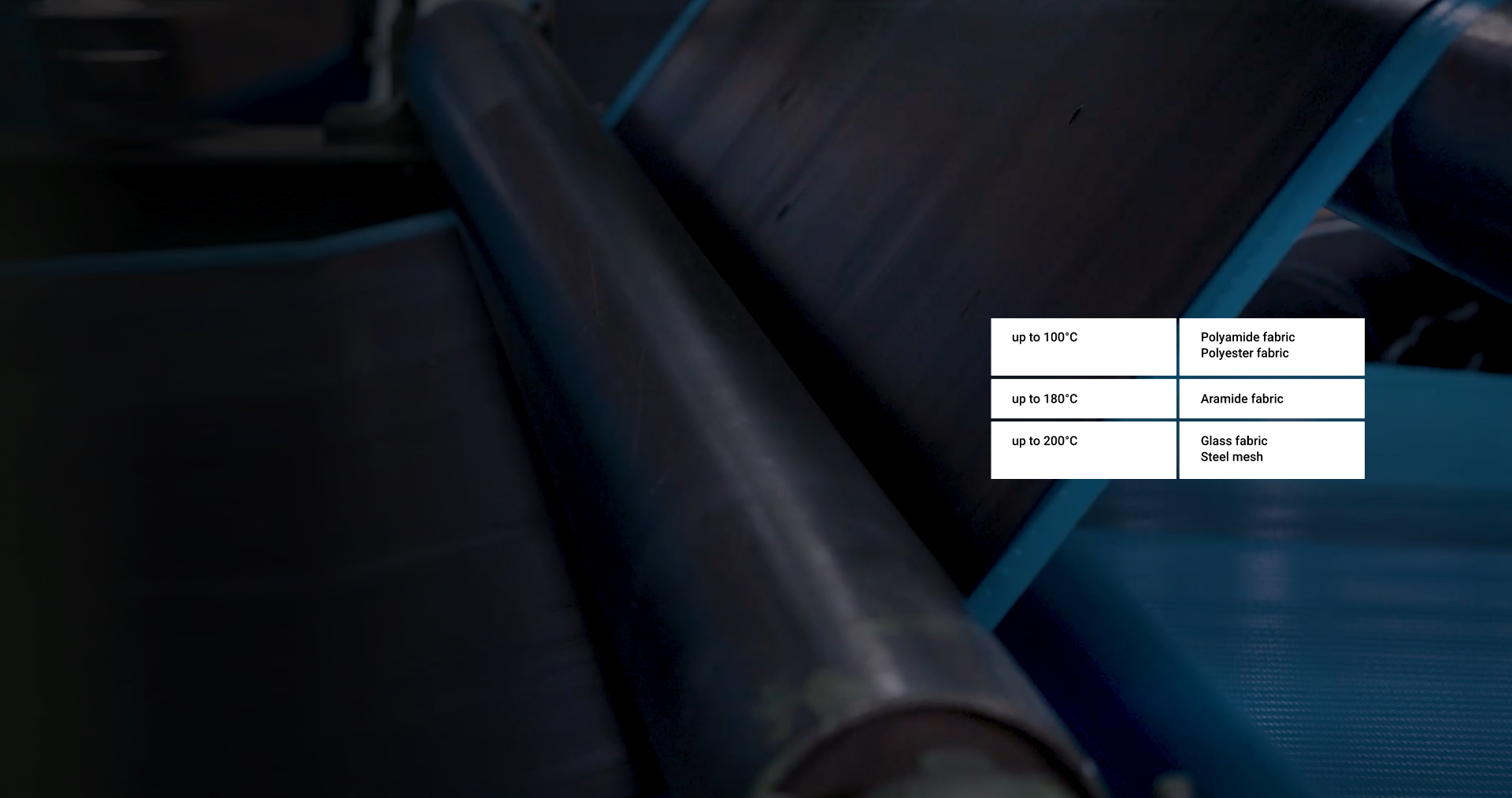
up to 200°C
Flange standard
DIN
, EN
, ANSI
, AWWA
, BS
, JIS
or customized

up to 1.50 bar
up to 140°C
clamped fixing


custom face-to-face
up to 0.25 bar
up to 400°C
self-sealing flanges with single or multi-part backing flanges
100 to 4,000 mm
up to 200°C
sleeve ends or flanges