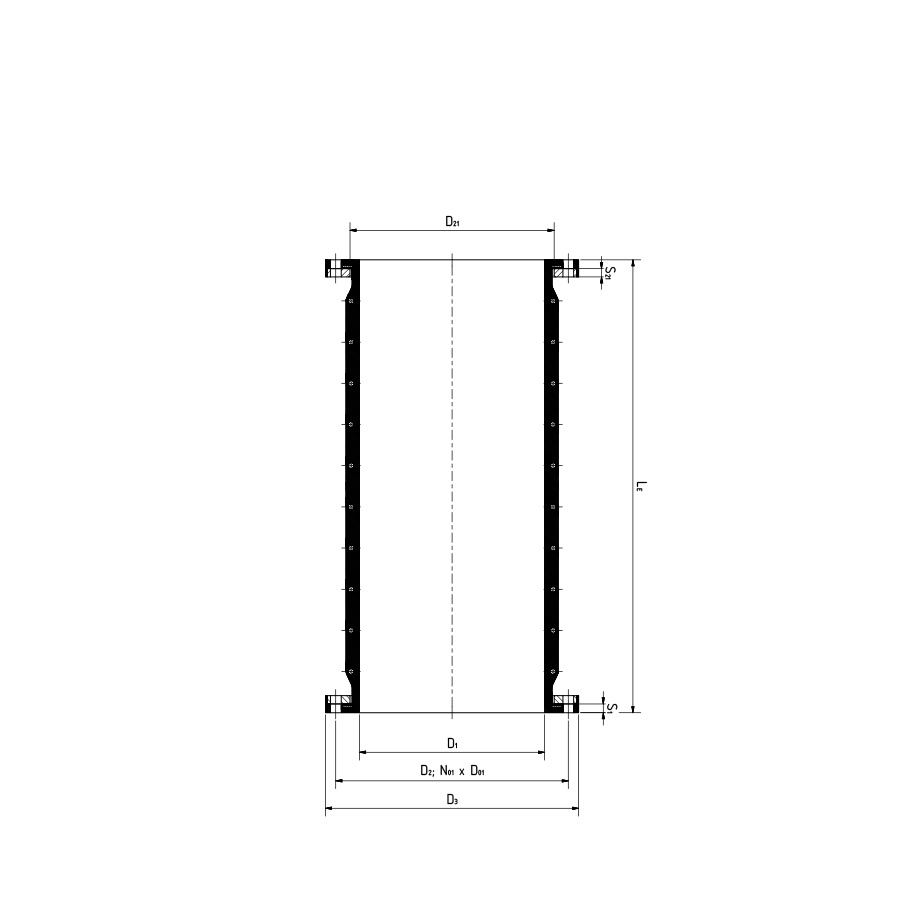
Models

U100A RFP

Universal archless spool type rubber pipe hose
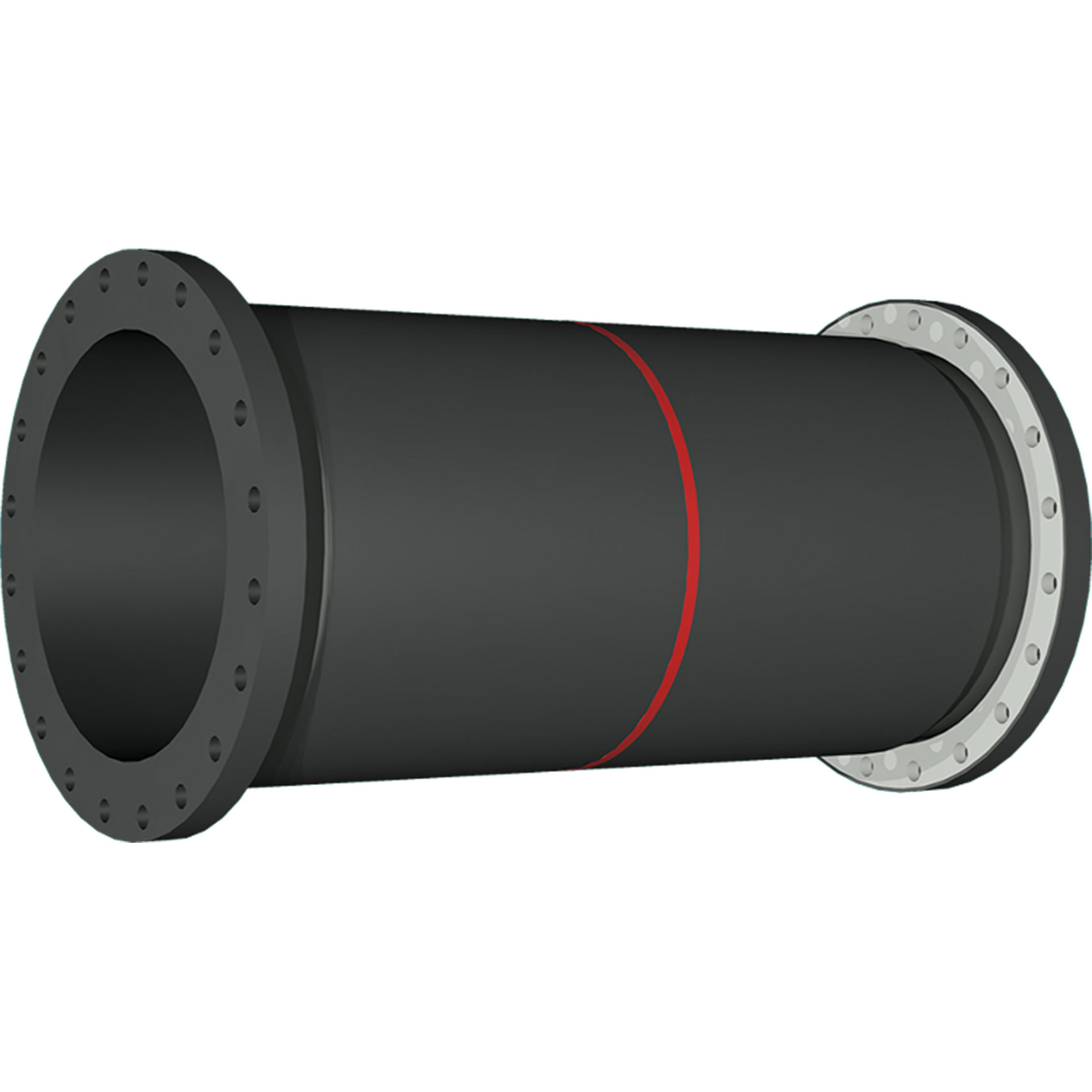
Technical data
Contact ditec

80 to 4,000 mm up to 7,000 mm up to 40 bar up to 200°C lateral and angular movement capability

Universal Expansion Joint

  • Universal Expansion Joint
  • Features & Benefits
  • Expansion Joint Thrust Calculation
  • Expansion Joint Spring Rates

Unrestrained expansion joint with one or more molded wide arches. 

Universal expansion joints are designed to absorb large all-directional movements, reduce noise and vibration, have a cycle life in the tens of millions, compensate for misalignments, provide access to piping and equipment and relieve pipe and anchor stresses.

A Universal Rubber Expansion Joint is a flexible connector fabricated of synthetic elastomers and fabrics and, if necessary, with metal reinforcements to provide stress relief in piping systems due to thermal and mechanical vibration and/or movements. 

This construction, as a standalone expansion joint, represents the most cost-effective arrangement when used in rigid piping systems with main anchors and numerous guides at specific spacing.

Explore Features & Benefits

Thermal movements along with other external forces and displacements, including ground settlement can quickly exceed allowable pipe and anchor stresses. Rubber expansion joints absorb these stresses and replace them with their own low stiffness (spring rate). 

The inherent flexibility of rubber expansion joints permits almost unlimited flexing to recover from imposed movements, requiring relatively less force to move, thus preventing damage to motion equipment. When expansion joints are installed in the pipeline, the static portion of the thrust is calculated as a product of the area of the inner diameter of the arch of the expansion joint times the maximum pressure that will occur with the line. The result is a force expressed in Newton which causes stress on the adjacent pipeline anchors. 

In order to reduce the forces, a lower arch can be used in case of small movements.

The spring rate is defined as the force in Newton required to deflect an expansion joint one millimeter in compression and elongation or in lateral direction. For angular movement the spring rate is the force needed in Nm to deflect the expansion joint one degree. 

These forces should be considered only as approximates which may vary with the elastomers and fabrics used in fabrication and depend from the specific construction type.The spring rate for a filled arch type expansion joint is approximately 4 times that of a standard single arch type. This rate is dependent upon the material used in the filled arch section of the expansion joint. The spring rate of a multi-arch type expansion joint is equal to the spring rate for a single arch type divided by the number of arches.

Expansion Joint Spring Rates

Pipeline Planning

  • Pipeline Planning
  • Combined Movement Calculation

The selection and application of expansion joints plays a significant role in system performance, quality and reliability. 

Leveraging our extensive industry experience since 1973, ditec uses a systematic approach to finding the optimal solutions for any piping system. We apply the most sophisticated analysis and calculation software tools such as Finite Element Analysis (FEA), 3D Modelling and CAD to select the most appropriate expansion joint to fit into the corresponding pipeline system.

Explore Pipeline Planning

Expansion joints take over axial, lateral  and angular movements as a result of thermal changes in pipeline length, prevent the transfer of mechanical vibrations from machines, apparatus or pumps on the connected pipeline and compensate for stresses or assembly imprecision.

The potential axial, lateral and angular movements are specified for the respective expansion joint systems. The combination of two or more movements is expressed as the resultant movement. To calculate combined axial movement and lateral displacement, the values drop.

Combined Movement Calculation


Bellows Construction

Our rubber expansion joint designs always comply with the European Pressure Equipment Directive PED 2014/68/EU for the specified operating conditions, follow the guidelines of the Fluid Sealing Association (FSA) Technical Handbook for Non-Metallic Expansion Joints and ASTM F1123 – 87 Standard Specification for Non-Metallic Expansion Joints.

Certificate PED 2014/68//EU

An expansion joint body is constructed as follows:

  • high-grade leak-proof medium-resistant internal tube (bore)
  • multiple layers of pressure-resistant high-strength tire cord fabric
  • weather, ozone and UV-resistant seamless external layer (cover)

Bellows Materials

  • Rubber Grades
  • PTFE Lining
  • Fabric Reinforcements
  • Metal Reinforcements

The rubber blends adapted to our requirements are obtained from reputable manufacturers. We work with them continuously to further develop and optimize the blends. The physical and chemical properties are specified in detail in the materials datasheets and every batch of rubber delivered is subjected to extensive goods receipt inspections. 

Rubber Grade Table

Explore Rubber Shore Hardness

If it is not possible to select a rubber grade that will endure for the long term due to the corrosiveness of the medium or the diversity of materials being conveyed, we can provide expansion joints with an interior fluoroplastic lining of PTFE / FEP.

Explore PTFE Lining

The reinforcements of the rubber bellows are high-quality synthetic fabrics which bear the forces from the internal pressure or vacuum. The type, quantity and arrangement of the reinforcements are designed in keeping with Pressure Equipment Directive PED 2014/68/EU. All carriers are impregnated with rubber, completely embedded in the bellows and are firmly connected to the body. 

Wire or solid steel rings made from carbon or stainless steel embedded in the bellows construction are used as strengthening members of the expansion joint. A steel ring embedded in the top of the bend prevents the expansion joint body from collapsing under vacuum; it has no media contact and is not washed around by flow turbulence. Special packing and transport means must be considered for very large dimensions because the bellow with embedded steel ring cannot be squeezed anymore.

Flange Fixing Technology

  • Flange Fixing Technology
  • GRP Pipe Specialities
  • Flange Standards

A full face integral rubber flange design with backing flanges is available for types without, with single and multiple arch design. The rubber flange of the bellows is molded in an equal thickness to the flange diameter.

Full face rubber expansion joints are self-sealing. So an additional separate gasket is not required.

Explore Flange Fixing Technology

Flanges of glass reinforced epoxy piping (GRP) cannot withstand the required tightening torques of full-faced rubber expansion joint fixed to without cracking depending from design pressure and pipe standard. In order to avoid special measures on the GRP pipe flange ditec has developed a special sealing technology in the bellows rubber flange to lower the torques by approx. 50 %. This also eliminates the need for any grooves for O-rings in the GRP flange and the most economic flat face GRP flange can be applied.

Expansion joints in GRP pipelines with collar flange fixing and backed steel rings the rubber flange surface shall have a raised face up to the outer diameter of the GRP stub to avoid cutting of sharp edges into the rubber. 

GRP Flange Specialities

We can furnish all our expansion joint types meeting the following drilling/flange standards, among others.

  • DIN = Deutsches Institut für Normung
  • EN = European Norm
  • AWWA = American Water Works Association
  • ASME = American Society of Mechanical Engineers
  • API = American Petroleum Institute
  • MSS = Manufacturers Standardization Society
  • BS = British Standard
  • JIS = Japan Industrial Standard

For custom drilling or flange data not shown, please contact us.

Flange Standard Tables

Vacuum / Support Rings

Rubber expansion joints can be equipped with internal vacuum spirals, vacuum rings and/or external support rings/ropes to protect against deformation of the expansion joint bellows depending on the operating pressure. The diameters of the rings are individually designed and calculated against deformation under full vacuum respectively against test pressure considering extra safety margins.

Explore Vacuum / Support Rings

Flow Liners

  • Flow Liners
  • Design Details

Rubber expansion joints have streamlined arch contours in order to reduce pressure drop (resistance coefficient ζ), turbulence and flow losses. In most cases it is possible to use them without an additional flow liner. This is only needed for abrasive media and for flow speeds of more than 5 m/s. The expansion joint bellows should then be fully protected by the flow liner. The sleeve extends through the bore of the expansion joint with a full faced flange on one end. It is constructed of metal, fluoroplastic or GRP. 

Flow Liner Variants

Bellows Resistance Coefficient ζ


The following points should be considered when designing flow liners:

  • The lateral displacement needs to be taken into account in dimensioning the flow liner and can in some circumstances lead to severe narrowing of the pipeline cross-section.
  • To avoid deposits between the flow liner and the expansion joint, the tube can be perforated multiple times around its circumference, so that the intermediate space is flushed out and no deposits are able to form in the dead spots. This type of sleeve should not be used where high viscosity fluids, such as tars, are being transmitted. These fluids may cause packing or caking of the open arch or arches, which reduces movements and in turn may cause premature expansion joint failures.
  • The flow liners are installed along with the expansion joint. An additional seal is required between the flow liner flange and the pipeline flange. This extra seal is workshop-side fixed on the flange of the flow liner already.
  • Expansion joints with a full faced rubber flange need a flow liner flange with holes while for expansion joints with a sealing bead the flow liner flange can be centered with the screws.
  • The medium’s direction of flow must be taken into account during installation.

Protective Shield Covers

  • Protective Shield Covers
  • Ground Protective Shield
  • Protective Shield or Cover
  • Fire Protective Cover

Extreme external influences require that the expansion joints be protected by special measures. Appropriate protective covers have been developed to this end: Ground Protective Shield, UV Protective Shield or Cover, Fire and Splash Protective Cover. 

These types of shields/covers, when manufactured from metal, have one end which is bolted to or clamped to the mating pipe flange. The other end is free, designed to handle the movements of the expansion joint.

Caution: Fabric covers have some insulating properties. It is not recommended to insulate over elastomeric expansion joints. Because temperature containment can accelerate the aging of the rubber and makes required inspections difficult.

A protective shield of metal is required when an expansion joint is installed underground. It protects against damage to bellows, dirt and earth pressure. 

Based on specified loads strength and static calculations define the thickness of the shield as well as numbers and dimensioning of the stiffeners. Made from galvanized / paint coated carbon or stainless steel, in two or more parts, affixes to the medium pipe with an integrated clamp.

Protective covers should be used on expansion joints that carry high temperature, corrosive media or to prevent from exterior damage such as extreme solar radiation or weather effects, mechanical impacts or chemicals. 

This cover will also protect personnel or adjacent equipment in the event of leakage or splash. Metal shields do not enclose the expansion joint and still allow ventilation while wrap around protective covers of impregnated fiberglass fully shield the expansion joint. Protective shields from metal are made from galvanized / paint coated sheets, with two or more parts, multiple one-sided attachment on the circumference.

Fire covers, designed oversize, are multilayer blankets made from coated glass fiber fabric and insulating layers. Protects against the effects of flame up to 800 °C for a duration of 30 minutes. Used in ships and for fire water supply lines in buildings.

Certificates & Tests

  • Certificates & Tests
  • Testing

The focus on quality has always been a central part of the ditec’s mission. We strive to provide services of consistently high quality that fully meet the expectations of our customers. Implementation and adherence to recognized quality assurance systems ensures that all processes have been accurately performed – starting from the initial review of the submitted specifications to their design, manufacturing, testing and documentation in accordance with the customers’ requirements. The accreditations and certificates we possess enable us to shorten lead times and optimize resources by performing testing and inspection procedures in-house.

Download Certificates

Innovations in our testing capabilities allow ditec to provide
more testing options including, but not limited to:

  • Hydrostatic pressure testing
  • Vacuum testing
  • Burst pressure testing
  • Cycle life testing
  • Spring rate testing
  • Movement capabilities testing
  • Elastomer chemical analysis
  • Fluid and chemical compatibility test
  • Electrical properties

Services

  • Services
  • Repair Service
  • Our Service Team

Expansion joints require proper storage, handling and installation procedures for optimal long-term performance. It is crucial that the pipe system runs smoothly without the risk of unexpected, problematic and costly shutdowns. To achieve a trouble free and reliable operation, all of the components of the system including the expansion joints must be well managed. ditec is proud to offer on-site supervised plant surveys and inspections in addition to troubleshooting training and expedited replacements.

Our comprehensive field services include:

  • Site visits
  • Dimensional verification
  • Visual and physical inspections
  • Installation and installation supervision
  • Offset measurements for custom rubber expansion joint fabrication
  • Troubleshooting and quick-turn expansion joint replacement
  • Service life expectancy and operating condition evaluations
  • Product Recommendations and engineering service

Repair of the existing expansion joint unit is often more effective than buying a completely new unit. For example, replacement of wearing parts such as the rubber bellow in an expansion joint unit can be the most efficient solution that ensures both cost savings and an extended service life.

We also service expansion joints that were not of our original manufacture. Knowing the backing flange dimensions of the installed unit our extremely flexible production is able to manufacture the rubber bellow accordingly so that they can be reused.

Explore Repair Service

Any services are performed by our service and engineering team or by trained representatives based in almost all European countries as well as in many non-European countries. This way you receive competent advice with a guaranteed fast response time.

The team has experience in all industries and has attended several additional safety courses such as SCC, so they can easily meet all safety requirements demanded by customers.

Our engineers and installers are also authorized to enter Nuclear Power Plants and can carry out on-site planning and installation work inside of the containments.

We will gladly advise you

Your inquiry to us

Of course, we are also available to you as a contact partner for individual requirements and applications. 
This also applies to seemingly impossible cases - whether complex designs, special operating conditions
or extraordinary dimensions. Please contact us.

Universal Rubber Expansion Joints

Universal expansion joints are installed in piping systems that are anchored on both sides of the joint. This construction represents the most cost-effective arrangement when used in rigid piping systems with main anchors and numerous guides at specific spacing. They come as cylindrical, single, or multiple arch expansion joints with full faced rubber flanges, swivel flanges or as slip-on sleeves.

Cylindrical, single or multiple arch wall penetration seal

 200 to 4,000 mm  6,000 x 3,000 mm
standard 150 to 250 mm

up to 2.50 bar
with external pressure stability

up to 200°C

Flange standard
DIN , EN , ANSI , AWWA , BS , JIS or customized

Rubber belt between turbine neck and condenser

up to 1.50 bar

up to 140°C

clamped fixing

Elastomer or multilayer fabric ducting expansion joints

custom face-to-face

up to 0.25 bar

up to 400°C

self-sealing flanges with single or multi-part backing flanges

Disc bellows with custom number and depth of folds

 100 to 4,000 mm

up to 200°C

sleeve ends or flanges

U100A RFP

80 to 4,000 mm up to 7,000 mm up to 40 bar up to 200°C lateral and angular movement capability